Ring Oscillator
I built a 3-transistor ring oscillator from discrete components.
Unlike the 2-LED-flasher, there’s not a huge number of schematics floating around on the web, which is weird.
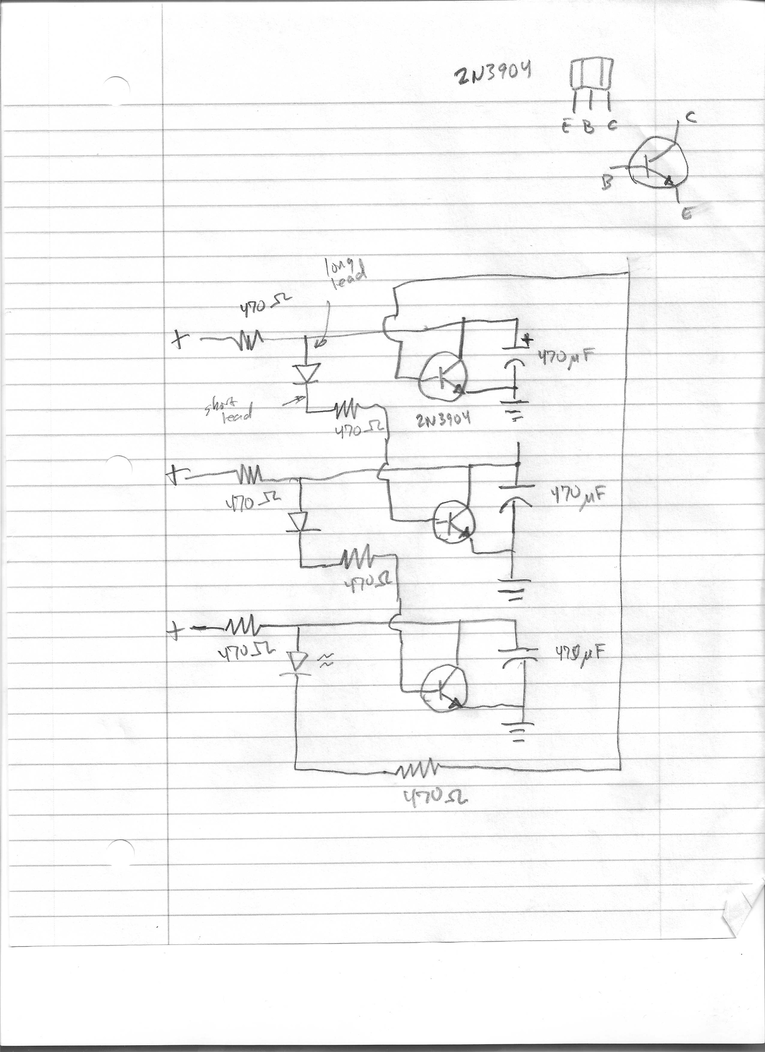
This is the schematic I reconstructed from a YouTube video:
Here’s the working breadboard:
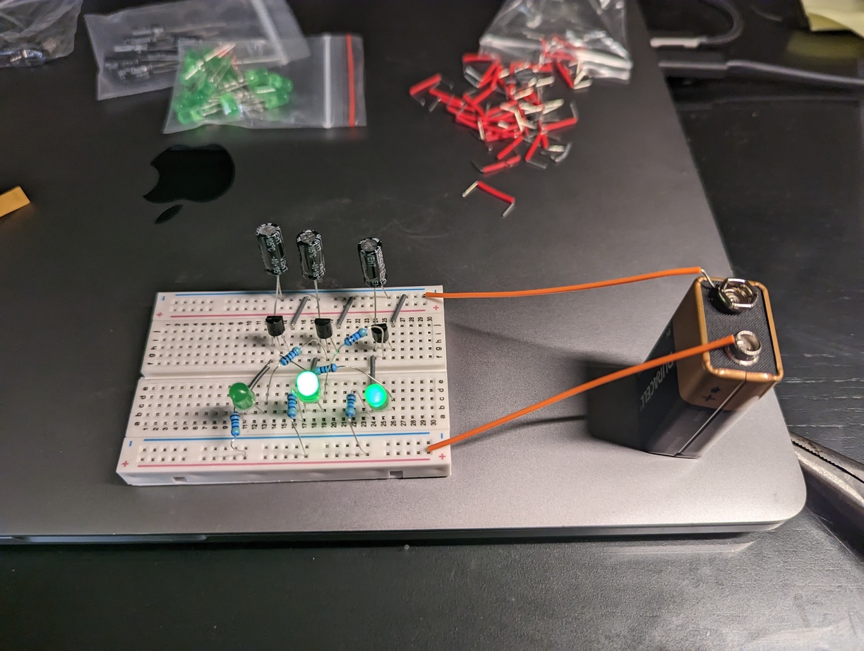
As you can see, at 9V it’s not working quite right. More than 1 LED is on at a time.
Oscillation starts at about 2.75V. It works great at lower voltages, 2.9 - 7V. You can clearly see that only 1 LED at a time is lit up. Above some limit, somewhere about 7.5V probably, the capacitors don’t seem to discharge fast enough, and more than 1 LED is on at a time. The LEDs are only in the circuit for illustration, and the capacitors are in the circuit to slow the oscillation.
At first I thought this was just the 2-LED-flasher with another “cell” inserted, but it’s not. The LEDs on the 2-LED-flasher are connected to the transistors’ base, while the ring oscillator has the LEDs connected to the transistors’ collector. I think the method of functioning is very different.